主要内容
预览文档 论文类型:毕业设计论文,适合集成电路设计、电子工程、微电子专业学生及滤波器设计相关研究人员参考。
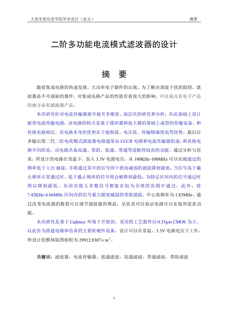
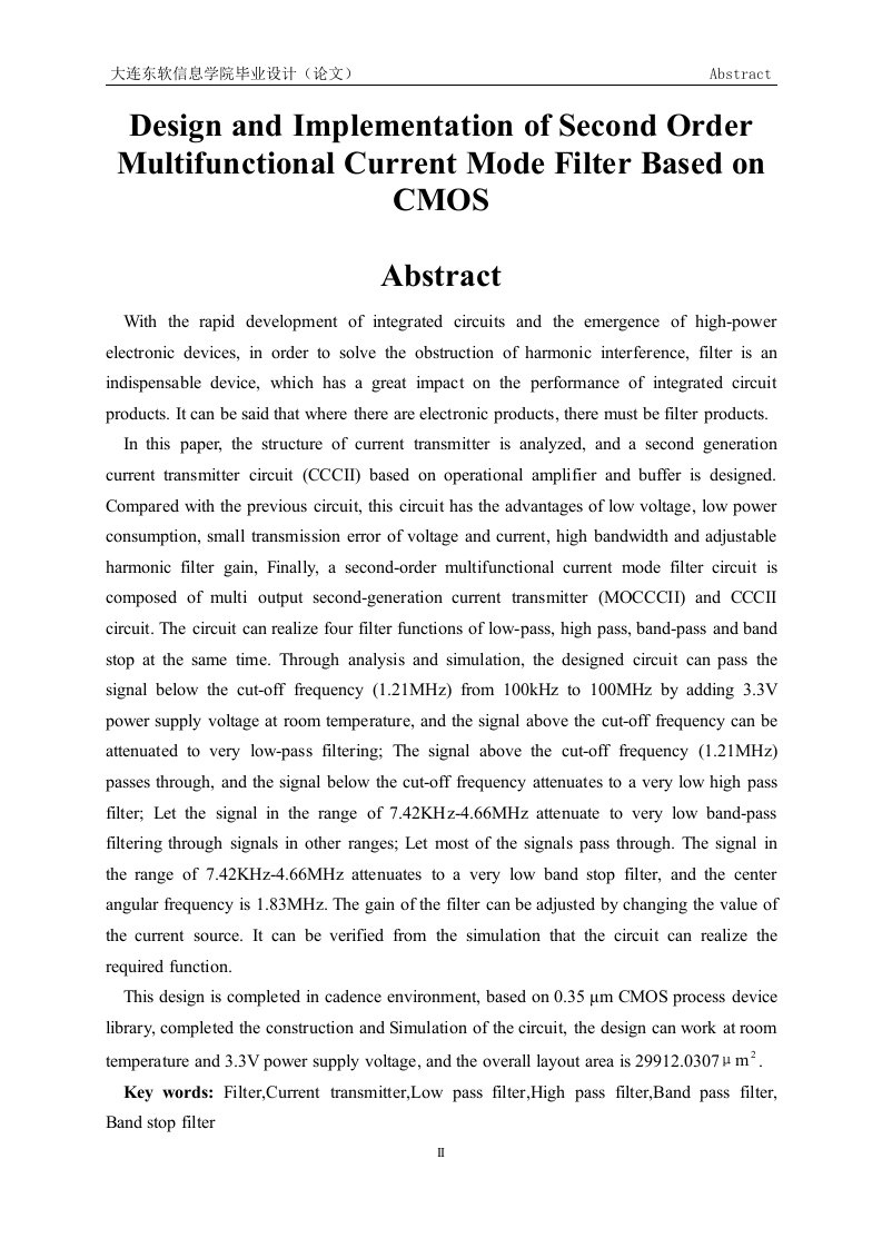
核心内容:该论文围绕基于CMOS工艺的二阶多功能电流模式滤波器展开设计与实现,重点解决传统滤波器在功耗、带宽及增益调节方面的局限性。论文首先分析了电流传输器结构,设计了一种基于运算放大器和缓冲器的第二代电流传输器电路(CCCII),该电路具备低电压、低功耗、电压电流传输误差小、高带宽以及谐波滤波器增益可调等优势。在此基础上,利用多输出第二代电流传输器(MOCCCII)与CCCII电路组合,构建出一个二阶多功能电流模式滤波器电路,能够同时实现低通、高通、带通和带阻四种滤波功能。
关键数据与结论:在室温条件下,电路采用3.3V电源电压,基于0.35微米CMOS工艺完成设计与仿真。仿真结果表明,低通滤波器可让100kHz至100MHz范围内低于截止频率(1.21MHz)的信号通过,高于该频率的信号被衰减;高通滤波器则允许高于1.21MHz的信号通过,低于该频率的信号被衰减;带通滤波器使7.42KHz至4.66MHz范围外的信号通过,该范围内的信号被衰减;带阻滤波器则使7.42KHz至4.66MHz范围内的信号衰减,其余信号通过,中心角频率为1.83MHz。滤波器的增益可通过改变电流源数值进行调节,整体版图面积为29912.0307μm²。
实际解决问题:该设计为集成电路中谐波干扰的抑制提供了一种高效、可调的滤波方案。通过单一电路实现四种滤波模式,显著提升了滤波器的集成度与灵活性,适用于对功耗和带宽有严格要求的现代电子系统。论文从电路结构设计到仿真验证,完整展示了基于CMOS工艺的滤波器实现流程,对同类研究具有直接参考价值。
第1页 / 共34页
第2页 / 共34页
第3页 / 共34页
第4页 / 共34页
第5页 / 共34页
第6页 / 共34页
第7页 / 共34页
第8页 / 共34页
试读已结束,还剩26页,您可下载完整版后进行离线阅读
付费资源
© 版权声明
文章版权归作者所有,未经允许请勿转载。
THE END

暂无评论内容